|
|
|


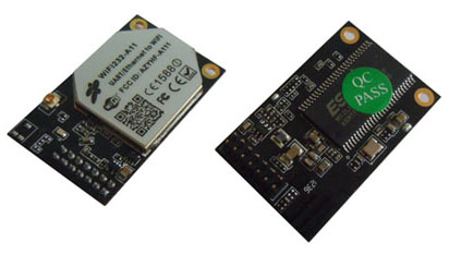
Wifi modules- Wifi-232-A11
Product Features:
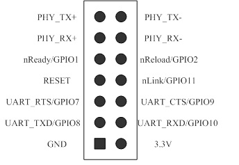
PIN Definition:
|
| © 2009 Shanghai Wafer Microelectronics Co.,Ltd. - Manufacturing GSM controllers ,gsm intercom,Coin Acceptor GSM Alarm and Automatic door Sensor. |
| ADD: 23E,Liang Feng Building , No.8, DongFang Road,Shanghai,China |
| Tel:+86-21-68458945 | Fax:+86-21-50454820 | Onservice Skype : wafer-service |
| Email:wafer@waferstar.com Links: www.huobei.net www.waferlife.com www.wafer-shopping.com www.mdb-rs232.com www.mdb2pc.com www.mdb-rs232.com www.mdb232.com www.mdbprotocol.com www.mdbprotocal.com www.mdbprotocol.cn www.gsmauto.cn www.letpos.com www.waferstar.com www.letalarm.com www.rtu5024.com www.rtu5015.com www.rs232-mdb.com www.intercom-gsm.com www.gsm-intercom.com 沪ICP备05023507号 |